Home Page
So I recently had a situation where I needed a cable but I couldn't work out which was the right one. I knew at least one of them was a null modem cable and my hope was that one of them was a CGA cable. Maybe one of them was a serial cable. How do I tell? None of them worked with my monitor. Part of the problem was that I needed a cable that was male at one end and female at the other and I could only achieve this by linking two together. Now I initially had a vague idea that the different types of cable are wired differently, while some have fewer wires in them than others. CGA is 'straight through' i.e. pin 1 at one end corresponds to pin 1 at the other end. This is not the case with a null modem cable and I have no idea about a serial cable. Being aware of this is all well and good but it doesn't tell me which cable is which if I can't see the wires inside the cable and where they connect. So here's how to tell.
 |
| A bunch of serial cables? Maybe not... [source: author] |
So I recently had a situation where I needed a cable but I couldn't work out which was the right one. I knew at least one of them was a null modem cable and my hope was that one of them was a CGA cable. Maybe one of them was a serial cable. How do I tell? None of them worked with my monitor. Part of the problem was that I needed a cable that was male at one end and female at the other and I could only achieve this by linking two together. Now I initially had a vague idea that the different types of cable are wired differently, while some have fewer wires in them than others. CGA is 'straight through' i.e. pin 1 at one end corresponds to pin 1 at the other end. This is not the case with a null modem cable and I have no idea about a serial cable. Being aware of this is all well and good but it doesn't tell me which cable is which if I can't see the wires inside the cable and where they connect. So here's how to tell.
Method 1: Visual Inspection
DE-9 cables are usually either male-male or female-female at either end. If they're male-female then it's likely (but not definitely) an extension and, therefore, straight-through. All serial ports on devices are male, so it can be safely assumed that a female-female cable is some kind of serial or modem cable (there's more than one). It thus follows that, because CGA/EGA ports on PCs are female, it could be assumed that the corresponding cables are male-male. This is where it gets tricky though, so visual inspection is of limited use.
Method 2: Dismantlement
Yeah I probably made that word up but you know what I mean. One of the cables had removable covers at each end, so I took 'em off and had a butchers:
You can see quite clearly that the pin assignments at each end differ. Also note how the shielding of the cable is soldered to the shell at each end. Just by visually inspecting the cable, I was able to map out the pin assignments on a handy bit of paper. The pin numbers are indicated on the plastic next to each pin in the socket:
As I said, clearly not straight through, so not a CGA cable. It's also not the cable in the photo above, just an example of the process. So what kind of cable is it? Well apparently the one I've mapped out here is a null modem with full handshaking [source: lammertbies.nl]. I'm sure this will be useful someday but, right now, it's bloody useless.
 |
| A dismantled serial cable [source: author] |
 |
| Wiring diagram of null modem cable [source: author] |
As I said, clearly not straight through, so not a CGA cable. It's also not the cable in the photo above, just an example of the process. So what kind of cable is it? Well apparently the one I've mapped out here is a null modem with full handshaking [source: lammertbies.nl]. I'm sure this will be useful someday but, right now, it's bloody useless.
Method 3: Measurement
The next two cables could not be dismantled without destroying them, as they were factory-moulded. Time to get the multimeter out.
By setting the multimeter to measure resistance, we can work out which pin is connected to which pin. Because the probes aren't slim enough, I broke a paper clip in half and shoved them into pin one on both ends. I could then connect the probes to the metal and measure resistance between each end. 1 means infinite resistance in other words no electricity is flowing. In this case, that means no connection. On the left I kept the positive probe on pin 1 and moved the negative probe to pin 2. I did this with every pin combination. Why didn't I stop when I find a connection? Because some leads are connected to more than 1 pin, that's why. When you find a connection, the resistance will reduce from infinity to negligible (or zero, depending on the sensitivity of your equipment). You'll get a rough idea of how many wires there are. Some serial cables only have 3 so watch out:
As you can see here, we have a connection between pin 6 and pin 4. If I were to swap them over we would also find a connection between pin 4 and pin 6. After testing every pin, I used a neat, free, open source program called TinyCad [source: sourceforge.net] to draw the diagrams below:
As you can see, this differs slightly from the first cable (and is the first cable I photographed). Apparently this is a null modem with partial handshaking. Again, bloody useless. The third cable, however, was quite a different result. For a start, both ends are male, which is a clue all by itself. It didn't take me long to establish that this cable is indeed straight through and exactly what I'm looking for!
Now the only issue I have is that one end of my cable is the wrong gender. I'm not buying some adaptor from a shop because I'm brassic. Instead, I'll take the dismantleable cable I've got and resolder it so it's also straight through. The only issue with that is that there are only 7 wires and I've got 9 pins to worry about. So now I need the CGA pinout to find out what's what:
As you can see, I've included the EGA pinout as well for comparison. The original MDA (monochrome graphics adaptor) only used 5 of the 9 pins available, with pins 2-5 having no connection. CGA stopped using pin 7 for video and instead assigned RGB signal to 3, 4 and 5 respectively. This leaves 2 and 7 unconnected and that happens to be 7 pins in total. Bingo!
There is one drawback. Although EGA uses DE-9 too (yes, DE-9), it needs those two extra pins (and hijacks the 6th pin, formerly used for intensity in MDA) in order to provide support for 2 bits per colour (hence two pins per colour). There are certain circumstances where the two can be interchanged but that would depend on compatibility between the monitor and the graphics card. If I wanted to maintain compatibility with MDA I would also need pin 7 but this will be exclusively CGA so I don't care.
Right, where's my soldering iron...
So here is the result of my meddling (no such thing as 'meddlings' apparently, but I think it sounds better). Pins 7 and 8 were already linked by a blob of solder, which is no skin off my nose considering 7 is unused. I snapped the covers back on the cable, plugged it in and...
Nothing.
Took me a good 15 minutes to remember that there's a switch on the front panel of the 1084 where you can choose which input to display (like every other bloody monitor - what an idiot!). Anyway it's not like I rewired the cable for nothing - it still wouldn't have worked even with the monitor on the right input selection. So now it works like a charm. I think I'll do another article soon on the differences between CGA composite and RGB.
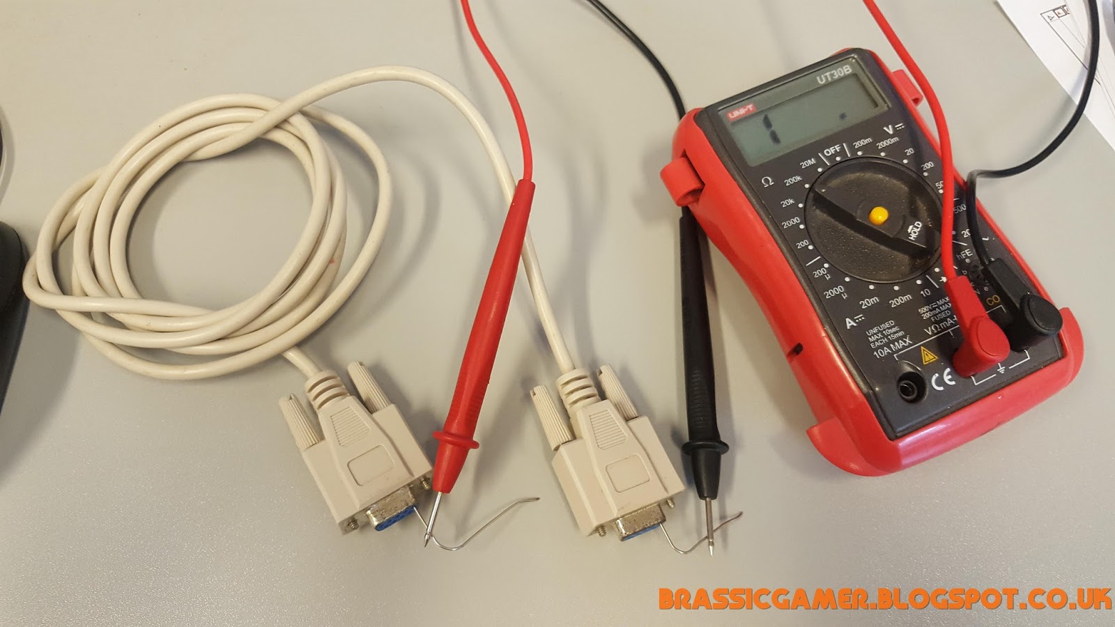 |
| Finding out which pin connects to which [source: author] |
By setting the multimeter to measure resistance, we can work out which pin is connected to which pin. Because the probes aren't slim enough, I broke a paper clip in half and shoved them into pin one on both ends. I could then connect the probes to the metal and measure resistance between each end. 1 means infinite resistance in other words no electricity is flowing. In this case, that means no connection. On the left I kept the positive probe on pin 1 and moved the negative probe to pin 2. I did this with every pin combination. Why didn't I stop when I find a connection? Because some leads are connected to more than 1 pin, that's why. When you find a connection, the resistance will reduce from infinity to negligible (or zero, depending on the sensitivity of your equipment). You'll get a rough idea of how many wires there are. Some serial cables only have 3 so watch out:
 |
| We have a match, but the pins are different numbers [source: author] |
As you can see here, we have a connection between pin 6 and pin 4. If I were to swap them over we would also find a connection between pin 4 and pin 6. After testing every pin, I used a neat, free, open source program called TinyCad [source: sourceforge.net] to draw the diagrams below:
 |
| Wiring diagram of null modem cable with partial handshaking [source: author] |
As you can see, this differs slightly from the first cable (and is the first cable I photographed). Apparently this is a null modem with partial handshaking. Again, bloody useless. The third cable, however, was quite a different result. For a start, both ends are male, which is a clue all by itself. It didn't take me long to establish that this cable is indeed straight through and exactly what I'm looking for!
Now the only issue I have is that one end of my cable is the wrong gender. I'm not buying some adaptor from a shop because I'm brassic. Instead, I'll take the dismantleable cable I've got and resolder it so it's also straight through. The only issue with that is that there are only 7 wires and I've got 9 pins to worry about. So now I need the CGA pinout to find out what's what:
 |
| Pinout for CGA and EGA graphics standards [credit: what-when-how.com] |
As you can see, I've included the EGA pinout as well for comparison. The original MDA (monochrome graphics adaptor) only used 5 of the 9 pins available, with pins 2-5 having no connection. CGA stopped using pin 7 for video and instead assigned RGB signal to 3, 4 and 5 respectively. This leaves 2 and 7 unconnected and that happens to be 7 pins in total. Bingo!
There is one drawback. Although EGA uses DE-9 too (yes, DE-9), it needs those two extra pins (and hijacks the 6th pin, formerly used for intensity in MDA) in order to provide support for 2 bits per colour (hence two pins per colour). There are certain circumstances where the two can be interchanged but that would depend on compatibility between the monitor and the graphics card. If I wanted to maintain compatibility with MDA I would also need pin 7 but this will be exclusively CGA so I don't care.
Right, where's my soldering iron...
 |
| Rewired null modem cable for 'straight through' operation [source: author] |
So here is the result of my meddling (no such thing as 'meddlings' apparently, but I think it sounds better). Pins 7 and 8 were already linked by a blob of solder, which is no skin off my nose considering 7 is unused. I snapped the covers back on the cable, plugged it in and...
Nothing.
Took me a good 15 minutes to remember that there's a switch on the front panel of the 1084 where you can choose which input to display (like every other bloody monitor - what an idiot!). Anyway it's not like I rewired the cable for nothing - it still wouldn't have worked even with the monitor on the right input selection. So now it works like a charm. I think I'll do another article soon on the differences between CGA composite and RGB.